Why Do You Need a PCB Prototype?
A PCB design can look correct on a screen and still fail on the bench. A connector may sit too close to an enclosure wall, or a trace may behave differently under real loads. A pcb prototype turns those assumptions into something engineers can inspect, measure, and test before committing to larger production runs. It is a practical checkpoint, not a guarantee.
With a physical board, teams can verify component placement, solder joints, mounting holes, and cable access. They can also test power, signal quality, heat, and firmware interaction in the intended setup. A small prototype run may reveal a reversed footprint or a misaligned header while changes are still manageable. That feedback can reduce costly rework later, though results depend on the quality of the design and the tests performed.
Real hardware teaches quickly. Sometimes awkwardly. Engineers should record test conditions, measurements, and failures rather than relying on memory or a single successful power-up. A prototype may expose problems, but it cannot prove that every production board will behave identically. Materials, assembly processes, and component availability can change between builds. That part is easy to underestimate. Used thoughtfully, prototyping helps validate design choices, improve manufacturability, and give teams stronger evidence before release. It also creates space to question early assumptions—and revise them when the board says otherwise.
What a PCB Prototype Is and How It Differs from a Production Board
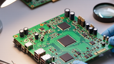
A PCB prototype is a working sample built to test a circuit’s layout, fit, and function before a design is repeated at scale. Engineers can probe a test pad, inspect a solder joint, or check whether a connector clears the enclosure. The prototype may use the intended layer count and materials, but it is not automatically equivalent to a production board. Small runs often allow manual assembly or design changes between builds. Production requires stable processes, repeatable inspection, and agreed acceptance criteria.
IPC-6012, an industry qualification standard, defines three performance classes for rigid printed boards, reflecting different end-use requirements. A prototype should be evaluated against the class and tests relevant to its intended application—not simply judged by whether it powers on. IPC’s North American PCB Statistical Program tracks reported orders, shipments, and book-to-bill ratios. Those industry indicators describe market activity; they do not prove that any individual board is production-ready. That distinction matters. A successful prototype can still reveal solder-mask clearance issues, marginal signal quality, or a footprint that is awkward to assemble. And a first build can be misleading. One board working on a bench is useful evidence, but it is not evidence of consistent performance across a production lot.
How a Prototype Tests a Circuit Design Before Manufacturing
A PCB prototype turns a circuit diagram into something engineers can inspect and measure. It reveals whether components fit, connections are correct, and signals behave as expected. A schematic can look tidy on a screen. The assembled board may tell a different story. Small details matter, such as a connector facing the wrong way or a test point hidden beneath a component.
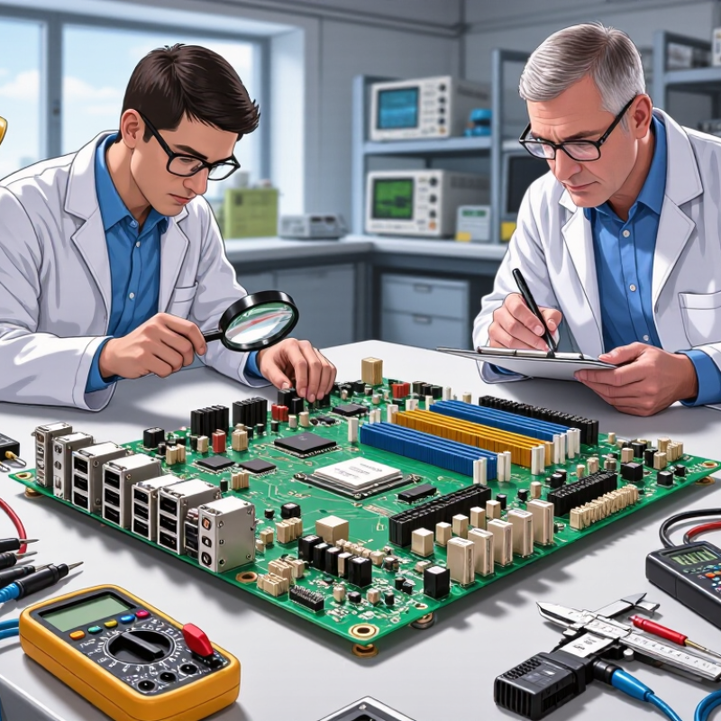
Testing begins with careful checks before power is applied. Engineers inspect solder joints, confirm key connections, and look for shorts with a multimeter. Then they power the board with a current-limited supply. An oscilloscope can show whether a clock is stable, while a temperature check may reveal an overheating regulator. These checks help catch faults before they affect a larger production run. A prototype is not a promise. It is evidence.
Testing should also reflect real operating conditions. A sensor board, for example, might be checked with different input levels and cable lengths. Engineers can compare measured voltages with expected values and note where results drift. Some problems only appear after the board warms up, or when several functions run at once. One prototype may not expose every weakness, and that limit deserves attention. A design may need another revision before its behavior is dependable.
Which Electrical and Physical Features Engineers Evaluate
A PCB prototype lets engineers compare electrical calculations with measurements from a real board. Check continuity, isolation between nets, and impedance on controlled-impedance traces. Record the readings, not just pass or fail. IPC-2221B provides a framework for board design, while IPC-6012E defines qualification and performance requirements for rigid printed boards. Their criteria help teams set acceptance limits before testing. Small details matter.
Physical checks are just as important. Measure board thickness, hole diameters, edge clearance, and component alignment against the drawings. Then fit the board into its enclosure and inspect connector access, screw holes, and clearance beneath tall components. A board may work on a bench yet collide with a case wall. That is an easy assumption to miss. Temperature cycling and vibration tests can also reveal cracked joints or weak mounting points; choose test conditions that reflect the product’s actual use.
Tips: Keep a test log with the instrument, setup, result, and revision number. Compare each prototype against IPC criteria and your own tolerances. A single successful board is useful, but it is not proof that every design assumption is sound.
How Prototype Testing Reveals Design and Assembly Problems
Why Do You Need a PCB Prototype?
Prototype testing turns a schematic and layout into a board you can inspect, measure, and assemble. It can reveal a reversed connector, a crowded solder joint, or a trace that runs too close to a mounting hole. These problems may look minor on screen, but they can cause rework or prevent assembly. An often-cited Aberdeen Group product-development analysis estimates that about 80% of a product’s cost is committed during design. That makes early checks valuable: moving a component is usually easier before a full production run.
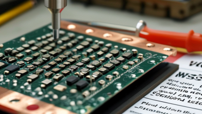
Test the board under realistic conditions. Check power-up current, signal quality, connector fit, and component temperature; inspect solder joints under magnification. Compare observed failures with the design files and assembly notes, then record each change. IPC-A-610 provides widely used acceptance criteria for electronic assemblies, helping teams assess workmanship consistently. A prototype still cannot predict every production variation. Sometimes the first board simply exposes a new question, and that is useful.
Tips: Photograph defects before rework. Mark the board revision, test conditions, and measured values. One detail is easy to forget: a passing test is only meaningful when the setup matches the product’s intended use.
When to Build a PCB Prototype During Product Development
A PCB prototype is most useful after the circuit architecture is clear, but before committing to production tooling or a large component order.
Build one when key assumptions need testing: connector placement, power delivery, signal integrity, heat, or firmware communication. WSTS’s Fall 2024 forecast projected global semiconductor sales of about $626 billion, up 19% year over year. That scale reflects a fast-moving component market; it does not, by itself, prove that prototyping saves money. It does underline why checking parts and footprints early matters.
Too early? Possibly. A board built before the interfaces settle may test little beyond unfinished decisions. Too late? Costly. Once enclosure tooling, cable lengths, and assembly plans are fixed, even a small connector change can ripple outward. A practical checkpoint is after schematic review and initial layout, when the team can assemble a small batch and measure actual behavior. Check voltage at the load, temperature near regulators, and whether the board fits its enclosure without forcing cables.
Use a first prototype to expose electrical and mechanical risks, then revise before design validation. Bring in firmware and manufacturing feedback while changes remain manageable. One imperfect board may reveal a wrong assumption; that is useful, not embarrassing. Still, a prototype cannot prove long-term reliability from a brief bench test. Record what was tested, what failed, and what remains unknown before approving the next build.