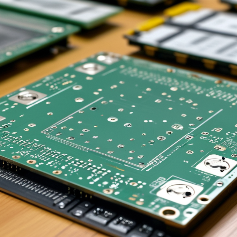
Choosing among the 10 Best PCB Prototype Services for Global Buyers requires more than comparing advertised prices. A reliable pcb prototype partner should understand engineering requirements, production risks, and international delivery realities. A four-layer FR-4 board with 1.6 mm thickness, controlled impedance, and 0.2 mm vias can expose major differences between suppliers. Details matter.
This guide examines prototype manufacturers through practical criteria, including DFM feedback, material traceability, solder-mask quality, AOI inspection, electrical testing, and documented lead times. It also considers how suppliers handle Gerber files, BOM updates, component substitutions, packaging, and customs paperwork. Experienced buyers know that a fast quotation means little if the factory misses an unmarked tolerance or changes a component without approval. Clear communication matters.
Still, no ranking can fit every project. A startup may value five-day assembly, while an industrial developer may need repeatability, test fixtures, and stable sourcing. A low unit price can hide setup charges, shipping delays, or weak inspection records. Promises vary. The strongest services usually explain limitations before accepting payment, provide sample evidence, and respond precisely to technical questions. Buyers should verify certifications, review recent customer feedback, and request a small trial order when uncertainty remains. This comparison aims to support careful decisions, not replace engineering review. Some recommendations may change as technologies, logistics costs, and supplier capabilities evolve. That uncertainty deserves attention.
10 Best PCB Prototype Services for Global Buyers?
PCB Prototype Service Categories: 2–20 Layers, HDI, Rigid-Flex, and Flex
Choosing among the 10 best PCB prototype services requires more than comparing prices. Layer count shapes signal performance, mechanical strength, and production risk. A reliable supplier should support boards from 2 to 20 layers with controlled impedance options. Request stackup drawings before ordering. Small details matter.
Two-layer boards suit sensors, simple controllers, and early functional tests. Four- to eight-layer designs often support compact digital products and cleaner power distribution. Higher-layer prototypes demand tighter registration and careful material selection. Ask for inspection records, cross-section samples, and realistic delivery dates. Promises can be optimistic.
HDI prototypes use microvias and fine traces for dense layouts. They can reduce board size, but fabrication rules become less forgiving. Rigid-flex boards combine stable rigid sections with bendable connections. Flex circuits work well in hinges, wearables, and narrow spaces. Bend radius needs practical testing, not only software approval.
Material choice also deserves scrutiny. Standard laminates may fit general prototypes, while high-frequency or high-temperature designs need specialized materials. Confirm copper thickness, surface finish, minimum spacing, and testing methods. Global buyers should check packaging, documentation, customs requirements, and communication hours. I still question any service that hides engineering limits behind fast quotations. A prototype should reveal weaknesses early, even when the result is inconvenient.
Indicative business-day ranges commonly used for global prototype planning. Actual timing depends on layer count, material, surface finish, quantity, testing, and design complexity.
For global PCB buyers, quality begins before fabrication. IPC-2221 guides board design, spacing, materials, and electrical safety. It helps engineers reduce clearance errors and thermal risks during layout. However, a compliant design can still fail without careful production control.
IPC-6012 defines qualification and performance requirements for rigid printed boards. It covers areas such as plating, dielectric structure, and mechanical reliability. IPC-A-600 gives visual acceptance criteria for finished boards. Inspectors may check solder mask, conductor edges, holes, and surface defects under controlled lighting. ISO 9001 adds a quality management framework, including document control, corrective actions, and traceability. In practice, I ask suppliers for inspection records, material certificates, and cross-section reports. These details reveal more than a polished capability chart.
Tips: Request the exact revision of each standard. Confirm whether testing applies to your batch. Review drill files, impedance notes, and stack-up drawings together. Ask how nonconforming boards are contained and reported. Small gaps matter. A supplier may claim broad compliance, yet interpret acceptance limits differently. I have seen preventable delays caused by unclear terminology and incomplete drawings. That experience is worth remembering. Standards support reliability, but communication still decides whether a prototype performs as expected.
| Rank | Generic Service Profile | Best Fit for Global Buyers | Typical Board Types | Typical Prototype Lead Time | Layer Capability | IPC-2221 Design Guidance | IPC-6012 Qualification | IPC-A-600 Inspection | ISO 9001 Quality System | Common Quality Controls | Buyer Verification Checklist |
|---|---|---|---|---|---|---|---|---|---|---|---|
| 1 | Quick-Turn Rigid PCB Prototype Service | Early-stage hardware validation and fast engineering iterations | FR-4, single-sided, double-sided, and standard multilayer rigid boards | Approximately 2–5 working days after design approval | 2–12 layers are commonly available; confirm the specific stack-up | Applicable Trace width, spacing, vias, creepage, and thermal design should follow the project requirements |
Usually available on request Confirm the performance class and qualification documentation |
Commonly used Visual acceptability inspection for workmanship and finished-board defects |
Verify current certificate Certification scope and validity must be checked |
Automated optical inspection, electrical testing, solder-mask inspection, and dimensional checks | Confirm stack-up, copper weight, surface finish, test coverage, and acceptance class |
| 2 | Low-Volume Multilayer Prototype Service | Functional prototypes requiring controlled impedance and higher routing density | 4–16 layer FR-4 rigid boards with plated through-holes and microvias where supported | Approximately 5–10 working days | 4–16 layers are typical for prototype production; advanced structures require review | Applicable Layer planning, dielectric spacing, via structures, and impedance requirements should be documented |
Relevant IPC-6012 requirements should be matched to the intended rigid-board construction |
Expected Acceptance criteria should be agreed before production |
Verify current certificate | Impedance testing, AOI, X-ray inspection where needed, electrical test, and cross-section review for selected builds | Request impedance coupons, cross-section reports, material data, and inspection records |
| 3 | High-Density Interconnect Prototype Service | Compact consumer, industrial, medical, and communication electronics | HDI rigid boards using laser microvias, sequential lamination, and fine-line routing | Approximately 7–15 working days | Commonly 4–14 layers, depending on microvia structure and material selection | Applicable Fine-line geometry, via-in-pad, thermal management, and manufacturability require detailed review |
Relevant Confirm whether the selected construction meets the required IPC performance level |
Expected Inspection criteria should cover microvia, annular ring, solder mask, and conductor conditions |
Verify current certificate | AOI, X-ray, microsection analysis, laser-drilled via verification, impedance testing, and electrical test | Verify microvia reliability data, sequential-lamination capability, material availability, and yield history |
| 4 | Controlled-Impedance RF and High-Speed Prototype Service | Wireless, networking, radar, instrumentation, and high-speed digital designs | High-Tg FR-4, low-loss laminates, RF laminates, and mixed-material constructions | Approximately 7–15 working days | 2–12 layers are common; material and stack-up selection strongly affect performance | Applicable Transmission-line geometry, reference planes, dielectric tolerances, and return paths require engineering control |
Relevant Qualification should reflect the selected laminate system and rigid-board construction |
Expected Conductor, plating, solder mask, and dimensional acceptability should be inspected |
Verify current certificate | Impedance coupons, TDR testing, dielectric review, copper-thickness verification, AOI, and electrical test | Request calculated and measured impedance values, laminate datasheets, and stack-up approval drawings |
| 5 | Flexible PCB Prototype Service | Wearables, compact assemblies, cable replacement, and moving applications | Single- and multilayer flexible circuits using polyimide-based materials | Approximately 7–15 working days | 1–8 layers are commonly offered; dynamic-flex designs need special qualification | Applicable Bend radius, flex zones, stiffeners, conductor geometry, and strain relief must be defined |
Confirm applicable scope Rigid-board IPC-6012 alone may not cover all flexible-circuit requirements |
Applicable with flex criteria Inspection should address coverlay, exposed conductors, wrinkles, and dimensional features |
Verify current certificate | Dimensional inspection, continuity testing, coverlay inspection, bend testing, and conductor evaluation | Confirm flex standard, bend-cycle expectations, stiffener materials, minimum bend radius, and test method |
| 6 | Rigid-Flex Prototype Service | Space-constrained products that combine mechanical flexibility and rigid component areas | Rigid-flex multilayer boards with flexible interconnect sections | Approximately 10–20 working days | Typically 4–14 total layers, subject to bend-zone and lamination design | Applicable Rigid zones, flex zones, bend radii, transition areas, and via placement require detailed design rules |
Confirm applicable scope Rigid and flexible portions may require different qualification criteria |
Applicable with flex criteria Inspection should cover layer registration, coverlay, stiffeners, and transition integrity |
Verify current certificate | AOI, continuity testing, cross-section analysis, dimensional checks, bend testing, and transition-zone inspection | Request approved fabrication drawings, bend-cycle data, material construction, and transition-zone inspection results |
| 7 | Metal-Core and Thermal-Management Prototype Service | LED lighting, power electronics, motor control, and heat-sensitive assemblies | Aluminum-backed, copper-backed, and thermally enhanced rigid boards | Approximately 5–12 working days | 1–6 conductive layers are common; multilayer thermal constructions require engineering review | Applicable Thermal paths, dielectric isolation, creepage, current capacity, and mechanical mounting must be considered |
Relevant Confirm the qualification requirements for the rigid-board construction and dielectric system |
Expected Inspection should include dielectric coverage, conductor condition, and flatness |
Verify current certificate | Thermal-resistance verification, dielectric withstand testing, electrical test, flatness measurement, and AOI | Request thermal conductivity data, dielectric breakdown results, metal-base thickness, and flatness limits |
| 8 | Heavy-Copper and High-Current Prototype Service | Power conversion, battery systems, industrial controls, and high-current distribution | Rigid boards with increased copper thickness, heavy plating, and reinforced current paths | Approximately 8–18 working days | 2–12 layers; outer and inner copper thickness must be specified separately | Applicable Current density, thermal rise, copper weight, spacing, via current capacity, and mechanical stress require analysis |
Relevant Confirm the required copper, plating, hole, and thermal-performance criteria |
Expected Inspection should address copper distribution, plating, conductor geometry, and board flatness |
Verify current certificate | Microsection analysis, copper-thickness measurement, thermal testing, electrical test, and dimensional inspection | Confirm finished copper thickness, via strategy, thermal-rise target, plating capability, and test-current limits |
| 9 | Automotive and Harsh-Environment Prototype Service | Products exposed to vibration, temperature cycling, humidity, chemicals, or extended operating life | High-Tg multilayer rigid boards, thermal boards, and selected rigid-flex constructions | Approximately 10–20 working days | 4–16 layers are common; material selection depends on temperature and reliability requirements | Applicable Thermal expansion, vibration, creepage, mechanical support, and reliability-oriented layout must be considered |
Relevant Use the appropriate performance class and supplement it with application-specific tests |
Expected Acceptance criteria should be defined for plated holes, solder mask, delamination, and dimensional stability |
Verify current certificate | Thermal stress, thermal cycling, humidity exposure, microsection analysis, AOI, and electrical test as specified | Request material traceability, reliability-test plans, process-change controls, and environmental test evidence |
| 10 | Regulated-Industry Documentation-Focused Prototype Service | Medical, aerospace, laboratory, and other products requiring strong configuration control | Rigid, flex, rigid-flex, and high-reliability multilayer boards subject to project specifications | Approximately 10–25 working days | Capability depends on the approved construction, material system, and documentation requirements | Applicable Design rules, revision control, manufacturability review, and traceable approval records are important |
Relevant Qualification level and supplementary customer requirements should be documented |
Required by specification Acceptance class, inspection method, and defect reporting should be agreed in advance |
Verify current certificate Check certificate scope, site, expiry date, and applicable manufacturing activities |
Full material traceability, first-article documentation, AOI, electrical test, microsections, and controlled nonconformance records | Request quality manual extracts, certificate copies, inspection plans, traceability records, and change-notification procedures |

A reliable prototype service starts with DFM review, not a low quotation. Engineers should check annular rings, solder-mask clearance, drill aspect ratios, and component spacing before release. IPC-2221 design guidance remains useful, but real factories interpret limits differently. Ask for marked-up Gerber feedback. Vague approval is a warning sign.
Impedance Control & Process Evidence Impedance control needs measured evidence. Request the stack-up, dielectric data, trace calculations, and test coupons. A practical target is often ±10% impedance tolerance, although high-speed designs may require tighter control. The 2024 Prismark PCB Industry Review valued global PCB production above 80 billion dollars, showing how small process differences can affect large supply chains. Yield data matters more than polished photographs. Ask for first-pass yield, scrap rates, and corrective-action records. The 2023 iNEMI Roadmap also stresses process capability for increasingly dense interconnects.
Lead Time & Factory Verification Lead time should include engineering review, material allocation, fabrication, testing, and shipping. A five-day build may become twelve days after questions and rework. I have seen schedules fail because buyers counted transit separately. That mistake is common. Compare quoted lead time with historical on-time delivery, not promises. IPC industry surveys regularly identify supply continuity and capacity as major electronics risks. Still, reports cannot replace a factory audit. Request recent inspection records, sample impedance reports, and one honest explanation of a failed batch. Perfect numbers deserve skepticism.
Global PCB prototype buyers should treat compliance as a design requirement, not a final inspection checkbox. RoHS controls restricted substances in electrical products, while REACH requires careful communication about substances of very high concern. UL recognition can support safety evaluation, but it does not automatically prove full product compliance. Ask for current material declarations, laminate data, solder-mask details, and traceable test records.
IPC Class 2 suits general commercial reliability, while IPC Class 3 demands tighter control for high-reliability applications. The difference can affect annular rings, plating quality, conductor spacing, and inspection depth. Small gaps matter. The European Commission’s 2023 Safety Gate report recorded 3,412 product alerts, with electrical equipment among frequently reported categories. That signal should influence prototype purchasing decisions. A low-cost board without controlled materials may create expensive redesigns later.
During supplier audits, compare certificates with the actual factory and production site. Check revision dates, scope, laboratory accreditation, and sample identification. I have found that paperwork can look complete while omitting the exact laminate or surface finish used. That weakness deserves attention. IPC’s electronics industry research also shows continuing supply-chain pressure, making documented traceability more valuable during substitutions. Buyers should define compliance evidence before fabrication, then verify it against the delivered boards. Ensuring every prototype meets UL, RoHS, REACH, IPC Class 2, or IPC Class 3 expectations remains a shared engineering responsibility.
A useful ranking must measure more than the advertised board price. It should include engineering review, fabrication, assembly, inspection, packaging, and delivery. Based on common prototype purchasing experience, the ranking is: 1) full-service engineering labs, 2) rapid multilayer specialists, 3) low-volume assembly houses, 4) quick-turn rigid-flex providers, 5) impedance-controlled manufacturers, 6) high-density interconnect specialists, 7) standard two-layer fabricators, 8) mixed-technology assembly shops, 9) small-batch domestic labs, and 10) entry-level quotation platforms.
Capability changes the result. A full-service lab may cost more initially, but its design-for-manufacturing review can prevent expensive revisions. A standard two-layer provider may win on simple sensor boards. For a six-layer controller, hidden costs appear quickly. Think solder-mask changes, component substitutions, stencil fees, customs paperwork, and reshipping.
Ask for a complete landed quote. Request stack-up details, material grades, tolerances, inspection records, and estimated yield. Check whether technical questions receive clear answers. Slow replies are a warning sign. Packaging matters too; crushed corners can erase a low quote. I have seen teams compare unit prices and ignore shipping delays, which was a costly mistake. The ranking also needs review after production, because the cheapest first order is not always the cheapest repeat order.