How to Choose PCB Manufacturing and Assembly in 2026
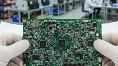
Choosing PCB manufacturing and assembly in 2026 requires more than comparing unit prices. The right supplier must balance engineering capability, production consistency, delivery speed, and long-term communication. A beautiful prototype means little if the factory cannot reproduce it at scale.
A practical evaluation begins with the board itself. Consider layer count, controlled impedance, fine-pitch components, thermal demands, and expected production volume. Ask how the supplier manages design-for-manufacturing reviews before fabrication. Clear feedback at this stage can prevent solder bridges, poor drilling results, and expensive redesigns. It also reveals whether the team understands real production constraints.
Quality evidence matters. Look for documented process controls, inspection records, traceability, and relevant certifications. Confirm whether automated optical inspection, X-ray inspection, and functional testing match the product’s risk level. Supply-chain visibility is equally important in 2026, especially for semiconductors and specialized laminates. A dependable partner should explain approved alternatives without quietly changing specifications.
The best pcb manufacturing and assembly provider will communicate clearly when problems appear. That sounds basic. It is not always common. Review sample reports, escalation procedures, engineering response times, and packaging methods. Ask for realistic lead times, not optimistic promises. A lower quotation may hide tooling fees, excess freight, or weak yield performance.
No scorecard is perfect. Technical teams can still overlook a connector shortage or an unclear tolerance. Build room for review, pilot production, and measured improvement. The strongest decision combines verified evidence with informed judgment, helping the final supplier support quality, compliance, and dependable product delivery.

Define Complexity: 1–6 Layers, HDI, Flex, or Rigid-Flex PCB
How to Choose PCB Manufacturing and Assembly in 2026
PCB complexity should guide your manufacturing decision. A one- or two-layer board suits simple sensors, relays, and low-speed control circuits. Four-layer construction gives power and ground planes, cleaner routing, and better electromagnetic control. Six layers may reduce congestion around processors, memory, and high-speed connectors.
Layer count alone does not define difficulty. HDI boards use microvias, fine lines, and tightly controlled registration. They can shrink a product, but they demand stronger process control and careful inspection. Flex circuits need suitable bend zones, soft coverlay, and a specified minimum bend radius. Rigid-flex designs add transition areas where copper, adhesive, and stiffeners must work together. These regions often deserve more attention than the schematic.
I have seen compact layouts fail because the mechanical model was treated as optional. A flex tail may look correct on screen, then crease beside a connector during assembly. A dense six-layer board may pass routing checks but leave no room for reliable soldering. Ask the manufacturer to review stackup construction, via filling, impedance targets, tolerances, and assembly access before releasing files. Provide the real enclosure, bend path, and expected production volume when possible. Prototype testing should include thermal cycling, repeated flexing, connector insertion, and visual inspection under magnification. Not every design needs HDI. Sometimes, a larger four-layer board is the more reliable and less expensive choice. Assumptions still need testing.
Verify Capability: IPC-6012, IPC-A-610 Class 2/3, and ISO 9001
When choosing PCB manufacturing and assembly in 2026, verify capability through standards, not attractive samples. IPC-6012 defines performance requirements for rigid printed boards, including materials, dimensional control, testing, and reliability. Ask for the exact revision used, not a generic “IPC compliant” statement. Review qualification records, process-control charts, and failure analysis reports.
IPC-A-610 Class 2 suits general electronics, while Class 3 demands tighter acceptance for products requiring continuous or critical performance. The difference appears in details: solder fillets, component alignment, lead protrusion, cleanliness, and board damage. Request recent inspection images and sample inspection records. IPC’s 2024 Electronics Industry Survey continued to identify cost pressure, delivery risk, and skilled-labor shortages as major industry concerns. Capability may therefore vary between shifts.
ISO 9001 certification shows that a quality management system is formally controlled. It does not prove perfect soldering or stable drilling. The ISO Survey 2023 recorded more than 1.26 million ISO 9001 certificates across 190 economies, showing broad adoption but not equal execution. Check the certificate scope, issuing body, audit date, and corrective-action history. I would also compare first-pass yield, defect rates, and customer-return data. Certificates can become comfort blankets. A factory may pass an audit while weak traceability remains hidden. Verify lot labels, material certificates, operator training, and escalation procedures before approving production.
Measure DFM Risk: 0.10 mm Spacing, AOI, X-Ray, and Test Coverage
Choosing PCB manufacturing and assembly in 2026 requires measuring DFM risk before requesting a quotation. A 0.10 mm spacing equals only 100 micrometres. Small contamination, etching variation, or artwork distortion can reduce that margin quickly. Check whether the fabricator controls line width, registration, copper thickness, and solder-mask alignment with recorded process data. IPC-2221 and IPC-6012 provide useful design and qualification guidance, but they do not replace supplier-specific capability evidence.
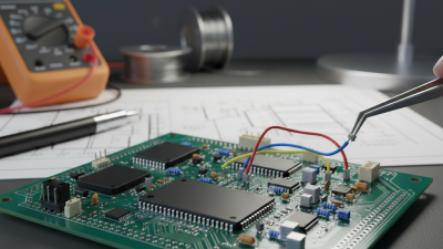
Ask how AOI is used, not merely whether it is available. AOI should inspect solder bridges, missing parts, polarity, tombstoning, and paste deposits. Request defect-classification records and false-call rates. IPC-9261 highlights the importance of measurable test effectiveness, while IPC-A-610 defines acceptance criteria for assembled boards. A practical review should connect AOI results with first-article inspection and corrective-action reports.
X-ray inspection matters when hidden joints exist, especially under bottom-terminated components or dense packages. Ask for sample images at production settings, not polished demonstrations. Electrical testing should include the actual coverage percentage, fixture limits, and untested nets. The 2024 IPC Global Electronics Industry Sentiment Survey continued to identify quality and supply reliability as major operational concerns. That supports stronger verification, though survey sentiment is not a substitute for factory data. I would not accept “100% tested” without a test map. Our own reviews sometimes overvalue inspection equipment and undervalue programming discipline. That remains a risk worth challenging.
Compare Total Cost: NRE, MOQ, 0201 Placement, Yield, and Lead Time
Choosing PCB manufacturing and assembly in 2026 requires a total-cost view, not a low quote. NRE usually includes tooling, stencil, programming, and engineering review. MOQ can also trap cash in slow-moving inventory. A supplier quoting 1,000 boards may appear cheaper, but storage and obsolete components can reverse the saving.
0201 components measure only 0.25 by 0.125 millimeters. Their placement demands accurate feeders, controlled solder paste, and strong inspection. IPC’s standards emphasize process capability and inspection discipline for miniature components. In practice, ask for first-pass yield data, not only placement-speed claims. A 98% yield sounds strong, yet it can create 200 defective boards in a 10,000-unit run. Yield definitions vary. Check whether rework is included. That detail is often missed.
Lead time has a financial value. The WSTS Spring 2025 forecast placed global semiconductor sales at about 698 billion dollars for 2025, with 11.2% annual growth. Demand shifts can extend component and assembly schedules. IPC’s 2024 electronics industry reporting also highlights continuing cost and supply-chain pressure. Compare quoted lead time with historical on-time delivery, not a single promise. I have seen buyers choose the lowest NRE, then pay more through delays, expedited freight, and line stoppages. A spreadsheet can still lie. Ask for a pilot run, measured 0201 yield, realistic MOQ flexibility, and clear ownership of rework costs before approving volume production.
Approve Production: IPC J-STD-001, First Article, and Lot Traceability
Choosing PCB Manufacturing and Assembly in 2026 requires more than comparing unit prices. Production approval should begin with IPC J-STD-001 requirements. This standard supports controlled soldering practices, suitable materials, trained operators, and measurable acceptance criteria. Ask the supplier for process records, operator training evidence, and inspection methods. A capable team can explain these details without hiding behind vague promises. Keep records clear.
Before approving volume production, require a documented First Article inspection. The first board should represent the exact materials, tooling, firmware, and assembly process planned for the lot. Inspect solder joints, component orientation, polarity, spacing, and cleanliness. Review X-ray or microscope images when hidden joints create uncertainty. Photographs help, but they cannot replace measurement data. If defects appear, pause approval and identify the process cause.
Lot traceability should connect each board to supplier lots, date codes, work orders, operators, machines, and inspection results. The record should also show rework, replacements, and final release authorization. Traceability is not paperwork alone. It reduces investigation time when a field issue appears. Still, paperwork can be incomplete or entered late. I have seen neat reports that failed to identify one substituted component. Leave room for skepticism. Verify records against labels, traveler documents, and physical samples before releasing production. A reliable approval decision combines standard compliance, direct evidence, and disciplined follow-up.