Top 10 Turning Tool Holder Types for CNC Machining
Choosing a Turning Tool Holder is not just a matter of matching a tool to a turret. The holder affects cutting stability, tool access, surface finish, and how quickly an operator can make a reliable setup. A rigid connection can help control vibration, especially when turning long workpieces or removing material with a heavier cut. Small details matter. Shank size, insert orientation, and clearance from the chuck can change whether a tool reaches the shoulder cleanly.
This guide reviews ten common turning tool holder types used in CNC machining, from general external holders to boring-bar and grooving styles. Each serves a different purpose. A right-hand holder may suit one cutting direction, while an offset or internal holder can reach features that standard tools cannot. The best choice depends on the machine, workpiece material, insert geometry, and operation—not on the holder name alone. Fit comes first.
For a practical comparison, check the holder’s dimensions and clamping method against the machine maker’s specifications. Consider coolant access, turret clearance, and the tool’s overhang before committing to a setup. These checks are easy to overlook when a job seems routine. Catalog descriptions can also make two holders sound more interchangeable than they are. A holder that performs well on a short, rigid setup may struggle with a long reach. There is no universal winner, and even a sound selection may need adjustment after the first test cut.
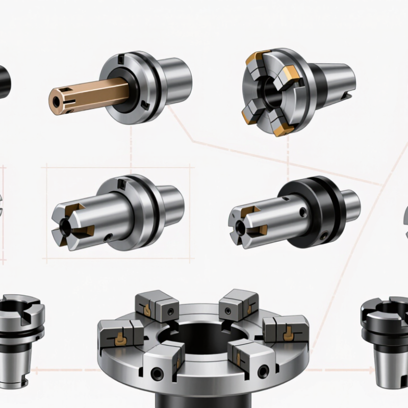
What a CNC Turning Tool Holder Does
A CNC turning tool holder connects the machine turret to the cutting insert, positioning the cutting edge at the programmed height and angle. It transfers cutting forces into the turret while helping limit deflection. On a steel shaft, looseness can appear as chatter, a rough spiral finish, or reduced insert life. Small details matter. Holder geometry sets approach angle and clearance, while through-tool coolant designs direct fluid toward the cutting zone. The holder cannot correct a poor setup, though. It is one link.
A rigid clamp helps operators replace inserts without rebuilding the entire setup, supporting repeatable automated cycles. The International Federation of Robotics’ World Robotics 2024 report recorded 4.28 million industrial robots operating worldwide in 2023. This provides broader factory context, not a measure of tool-holder performance. As shops automate more cutting cycles, stable tool positioning matters. Still, stiffness depends on the whole setup: turret, holder, insert seat, tool projection, and workpiece. A long overhang can vibrate. It is tempting to blame every chatter mark on the holder; that is too simple. Check runout, clamping, tool height, and workholding before changing holder style. The practical question is whether the holder suits the cut, access, and chip flow.
How Turning Tool Holders Are Classified by Design and Operation
Turning tool holders are best classified by how they position the cutting edge and what operation they support. Straight and offset holders place the insert at different distances from the turret, affecting clearance near a shoulder. External turning holders machine a workpiece’s outer surface, while boring bars carry an insert inside a drilled opening. Reach matters. A long boring bar may deflect, especially when its diameter is small.
Operation-specific designs include threading holders, grooving holders, cutoff holders, and facing holders. Threading holders orient the insert for a defined thread profile and pitch. Grooving holders guide a narrow insert into a controlled channel; cutoff holders are built to sever the part. Facing holders approach the end of the workpiece. These distinctions are useful, but not absolute: some holders can handle more than one operation when insert geometry and clearance allow it.
Mounting design adds another layer. Fixed holders rely on a stable clamp, while modular and quick-change systems allow faster tool replacement. Indexable-insert holders let machinists rotate or replace a worn edge without changing the whole tool. In practice, the best choice depends on the turret, material, cut depth, and chip flow. Check the setup at the machine. A holder that looks suitable on paper can still vibrate or collide with a shoulder. Classification guides selection; it does not replace a test cut.
Ten Common Turning Tool Holder Types and Their Uses
Turning holder choice affects access, chip flow, and surface finish. A straight holder handles general longitudinal cuts on a shaft. Right-hand and left-hand holders suit feeds in opposite directions, helping the insert approach a shoulder with clearance. Small details matter.
A boring-bar holder reaches inside a hole; keep its overhang short to limit chatter. A threading holder presents a sharp insert at the required thread angle. Grooving holders cut narrow recesses, while parting holders sever finished components. Their blades need firm support. Check the clearance.
Facing holders machine the end of a workpiece, moving the tool across its face. Profiling holders follow contours such as radii and tapers, though tight curves may demand careful path planning. Knurling holders press patterned wheels against the surface to create grip. These ten types cover common jobs, but names and setups can vary between shops. A holder that works well on a short, rigid part may struggle on a slender shaft; test the setup and inspect the finish before extending the cut.
How to Match a Holder to the Insert, Workpiece, and Machine
Top 10 Turning Tool Holder Types for CNC Machining
How to Match a Holder to the Insert, Workpiece, and Machine
Choosing a turning holder starts with the insert, not the catalog photo. ISO 1832 insert codes identify shape, clearance angle, tolerance, and fixing method; match these details to the holder’s seat and clamp. A mismatch can leave the insert unsupported or block chip flow. Check the approach angle against the shoulder, then confirm the holder clears the chuck and turret. Small clearances matter.
Workpiece material changes the choice. Long, slender shafts often need a rigid holder and a geometry that limits radial force; boring bars need enough reach without excessive overhang. On interrupted cuts, a sturdy negative insert may resist impact, but it also needs adequate machine power and setup rigidity. Don’t assume a larger holder always improves results. The Global CNC Machine Market report by Grand View Research valued the market at 101.22 billion U.S. dollars in 2023, reflecting broad investment in CNC capacity—not a guarantee that every machine can support heavy cuts. Test one setup.
Before production, inspect clamping contact, tool-center height, and chip evacuation on an actual workpiece. Record vibration, surface finish, and insert wear after a short trial. A holder that works well on a rigid turret may chatter on a compact lathe. That part is easy to overlook.
Top 10 Turning Tool Holder Types for CNC Machining
How to Match a Holder to the Insert, Workpiece, and Machine
Bars show the nominal included angle of the insert shape commonly paired with each holder style. Match the holder’s designation to the insert’s shape, clearance, and size; then consider workpiece profile, cutting direction, and machine clearance.
Key Factors in Selecting a Turning Tool Holder
Top 10 Turning Tool Holder Types for CNC Machining
Key Factors in Selecting a Turning Tool Holder
A turning holder should match the machine interface, insert geometry, workpiece material, and cut direction. Start with the job’s actual constraints: a tight shoulder may need a compact holder, while heavy roughing calls for a rigid setup. ISO 13399 provides standardized definitions for cutting-tool data, helping shops compare dimensions consistently. Still, a standardized catalog value cannot predict every machine’s behavior.
Overhang deserves close attention. The classical Euler–Bernoulli cantilever-beam model predicts deflection rises with the cube of unsupported length. Double the overhang, and predicted deflection can reach eight times more, assuming the same material and cross-section. That is a useful warning, not a shop-floor guarantee; holder shape, clamping, and cutting forces also matter. Measure stick-out at the spindle, not just at the insert.
Check coolant access, clearance, and insert seating before choosing a holder. A jet that misses the cutting edge is not much help. For internal turning, prioritize a bar diameter that fits the bore while keeping overhang short; for external work, verify the holder clears the chuck and finished profile. Record vibration, chip form, and insert wear during a test cut. Then adjust one variable at a time. I have seen a theoretically stiffer setup chatter because the real culprit was a worn clamp.