What Are the Top Extruder Machine Parts in 2026?

Extruder lines convert resin into film, pipe, sheet, and profiles, but steady output depends on more than the machine’s headline capacity. Extruder Machine Parts shape pressure, temperature, flow, and product consistency. In 2026, buyers and maintenance teams still need to assess screws and barrels, dies, heaters, gearboxes, screens, and drive systems as a connected assembly. Small choices matter. A worn screw can weaken melt quality; a poorly matched die can leave uneven edges or dimensions.

Industry data shows why reliable processing deserves attention, while not proving demand for any single component. PlasticsEurope’s Plastics—The Fast Facts 2024 reports global plastics production of 413.8 million tonnes in 2023. The OECD’s Global Plastics Outlook: Policy Scenarios to 2060 projects that global plastics use could rise from 460 million tonnes in 2019 to 1,231 million tonnes by 2060. These figures describe the wider plastics economy, not the extruder-parts market itself. That distinction matters.

This guide examines the parts most likely to affect uptime, product quality, and maintenance planning in 2026. It considers what each component does, which operating conditions can accelerate wear, and what buyers should check before replacing it. A screw designed for one polymer or throughput may not suit another line. Specifications are useful, but they cannot replace inspection and process experience. Even a good parts list has limits. Real results depend on resin, temperature, speed, and the condition of the full extrusion line.
What Are the Top Extruder Machine Parts in 2026?

Core Components of an Extruder Machine and Their Functions

What Are the Top Extruder Machine Parts in 2026?
Core Components of an Extruder Machine and Their Functions

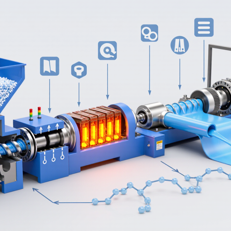
An extruder turns pellets into a controlled, continuous melt. Its hopper feeds material into the barrel, where a rotating screw conveys, compresses, and mixes it. The screw’s feed, transition, and metering sections each influence output and melt consistency. The barrel supports this work, while heaters and cooling channels help control temperature along the process. Small parts matter. A worn screw flight or poorly calibrated sensor can quietly affect product quality.

The drive and gearbox deliver the torque needed to rotate the screw under load. The U.S. Department of Energy’s Improving Motor and Drive System Performance sourcebook estimates that motor-driven systems account for about 68% of U.S. manufacturing electricity use, making drive efficiency worth monitoring. At the barrel outlet, a screen pack catches contaminants; rising pressure can signal a clogged screen. The die then shapes the melt into a profile, sheet, or strand. Heat is uneven. Operators should check readings across zones, not rely on one display.

Downstream equipment completes the line: cooling tanks or rolls set the shape, and a haul-off unit pulls material at a controlled speed. Plastics Europe’s Plastics—the Fast Facts 2024 reports global plastics production of 413.8 million tonnes in 2023. That scale makes dependable processing equipment important, though total production alone cannot predict a line’s needs. Even a well-designed setup needs regular inspection; real material behavior can be messier than a machine drawing suggests.


What Are the Top Extruder Machine Parts in 2026? Core Components and Their Functions

Typical single-screw design: indicative screw-zone lengths as multiples of screw diameter (D).

How to read it: The feed zone conveys and begins heating material, the transition zone compresses and melts it, and the metering zone helps deliver a more uniform melt. The hopper supplies material; the barrel and heaters support melting; the drive turns the screw; and the screen pack and die filter and shape the melt. Ranges are indicative design values, not universal specifications—actual geometry varies with polymer and application.

Feed Hoppers and Feed Systems for Supplying Raw Materials

Feed hoppers and feed systems control how steadily raw material enters an extruder. A hopper should hold enough material for continuous production without making refills awkward. Its outlet must match the material’s flow behavior. Fine powders may bridge above a narrow throat, while pellets usually flow more freely. It can still happen. A steep wall, smooth interior, and correctly sized outlet can reduce interruptions, but material trials matter.

The feeder then meters material toward the barrel. Volumetric feeders use screw speed to estimate output, while gravimetric systems adjust delivery by monitoring weight. The right choice depends on how closely the process must hold a feed rate. For blends, separate feeders can help maintain a consistent ratio. Keep dust extraction, guards, and refill access in the design; a difficult cleaning routine is often neglected until changeover takes too long. Check for worn screw flights, blocked outlets, and fluctuating weight readings during routine inspections. Moisture can also affect flow, so storage conditions deserve attention. A practical setup is rarely perfect on the first run. Operators may need to adjust feed rate and hopper geometry after observing real material behavior.

Screws and Barrels for Conveying and Plasticizing Materials

What Are the Top Extruder Machine Parts in 2026?

Screws and barrels remain central to conveying and plasticizing materials. The screw moves feedstock forward while heat and mechanical shear soften it. Its feed section accepts pellets, flakes, or another suitable material. The transition section gradually reduces channel depth, helping build pressure and melt the feed. At the metering end, a more consistent melt can support steadier output. Small details matter. Screw geometry must match the material and process; one design rarely suits every job.

The barrel surrounds the screw and helps contain pressure while transferring heat. Its internal surface and the screw’s flight edges experience friction, so wear can change output and melt quality over time. Operators can watch for changes in throughput, motor load, or temperature stability, then inspect dimensions during planned maintenance. A steady process is the goal. But temperature readings alone do not explain every problem: feed variation, moisture, and worn clearances can also affect results. It is easy to blame the screw too quickly. A careful check of material condition, operating records, and screw-barrel wear gives a more reliable diagnosis.

Drive, Heating, and Control Systems for Managing Extrusion

An extruder’s drive system must deliver steady torque as material resistance changes. The motor, gearbox, coupling, and screw work together to keep output consistent. A motor speed display alone cannot show whether the screw is under strain. Operators should also watch for unusual vibration, rising gearbox temperature, or changes in melt output. Small details matter.

Heating and control systems shape the melt across the barrel. Separate heater zones allow gradual temperature changes, while thermocouples report conditions near each zone. Heat is not uniform. A sensor can read normally even when material near the screw is overheating or cooling unevenly. Check sensor placement and compare readings with melt quality, not just the setpoint. That can mislead.

A well-configured controller coordinates screw speed, temperature, and alarms without hiding process changes. Clear alarms help operators respond before a minor drift becomes inconsistent product. Records of settings and maintenance can also reveal recurring patterns. No system is perfect. Sensors age, heaters fail, and material behavior varies. Regular checks of wiring, connections, and calibration help keep these parts dependable.

Dies and Calibration Units for Shaping the Final Product

Extruder dies and calibration units turn a molten stream into a product with defined shape and dimensions. A die distributes melt through channels; uneven flow can create thin walls, rough surfaces, or distorted profiles. PlasticsEurope’s Plastics – the Fast Facts 2024 reports 413.8 million tonnes of global plastics production in 2023. That figure covers plastics production broadly, not extrusion alone, but it shows the scale behind consistent processing. Small defects matter.

For film, pipe, and custom profiles, die design must match material behavior, output rate, and cooling conditions. Operators check melt pressure and temperature, then inspect the first pieces for drag marks and uneven edges. A clean die can still be misaligned. That is easy to miss during a rushed changeover.

Calibration units hold the product’s dimensions while it cools, often using vacuum, water, or both. On a pipe line, a blocked vacuum hole can leave a shallow surface mark; inconsistent water flow may pull the shape out of round. Measure samples at several points, not just near the line exit. The PlasticsEurope report also notes that recycled plastics represented 8.7% of global plastics production in 2023. Recycled feedstock can vary, so crews may need to adjust temperatures, vacuum, and line speed. Not every adjustment works on the first pass. Keep the readings.

What Are the Top Extruder Machine Parts in 2026? — Dies and Calibration Units for Shaping the Final Product

Machine Part Main Function Common Construction Key Design or Operating Considerations Effect on the Final Product
Extrusion Die Shapes the softened polymer melt as it exits the extruder. Machined tool steel; flow surfaces may be polished or coated to suit the material and process. Die geometry, flow-channel balance, temperature control, and die-gap uniformity must match the polymer, output rate, and product dimensions. Determines the initial profile, sheet, film, or tube shape and influences surface finish and dimensional consistency.
Pipe and Tube Die Head Distributes melt around a mandrel to form a hollow product. Steel die body with a central mandrel and annular flow channel. Concentric alignment and balanced circumferential flow help maintain an even wall; die design must account for melt swell and drawdown. Affects pipe diameter, wall-thickness uniformity, and the risk of uneven flow lines.
Profile Die Produces solid or hollow cross-sections such as trim, channels, or window profiles. Precision-machined steel tooling, often with separate flow paths for complex sections. Flow balancing is important because thick and thin sections cool at different rates. Die adjustment and temperature control may be needed during setup. Influences cross-section accuracy, corner definition, and the likelihood of warping or uneven dimensions.
Flat Die Spreads melt across a wide, narrow opening for sheet or film production. Steel die with a manifold and an adjustable or fixed lip. Uniform melt distribution across the die width and stable die-lip temperature help control thickness variation. Contributes to sheet or film gauge uniformity, edge quality, and surface appearance.
Die Lip and Adjustment Hardware Fine-tunes the die opening and, on some dies, corrects local output variation. Precision-machined die lips with mechanical or thermal adjustment features, depending on the die design. Adjustments should be small and controlled; operating temperature and mechanical stability affect repeatability. Can help improve thickness or profile consistency, but cannot compensate for every upstream flow or material problem.
Calibrator or Sizing Sleeve Supports and sizes an extruded product immediately after it leaves the die. Often made from stainless steel or other wear-resistant materials; contact surfaces and openings are designed for the product geometry. Its dimensions must suit the product and process. For vacuum sizing, the sleeve works with controlled vacuum and cooling. Helps establish outside dimensions and maintain the intended shape while the material cools.
Vacuum Sizing Tank Applies vacuum and cooling to hold a profile or pipe against its sizing surfaces. Sealed tank with vacuum connections, water circuits, and product-supporting sizing tooling. Vacuum level, water temperature, spray or flow distribution, and line speed need to be set for the product and material. Supports dimensional stability and cooling; uneven conditions can contribute to ovality or surface defects.
Cooling and Calibration Unit Continues cooling and supports the product after initial sizing. Water-cooled tanks, spray sections, or calibrated support elements, depending on the extrusion line. Cooling capacity and support layout should match product thickness, material, and production speed. Helps the product retain its dimensions as it solidifies and moves toward downstream haul-off equipment.

Part designs and operating settings vary by polymer, product geometry, line configuration, and production rate. The considerations shown are general selection and setup factors, not universal setpoints.

Wordpress Social Share Plugin powered by Ultimatelysocial
Facebook
X (Twitter)
YouTube
LinkedIn
Share

Purchase Product Request

Request Pricing