How to Choose the Right Grounding Kits?

Choosing the right Grounding Kits is not a simple matter of selecting the largest clamp or the lowest price. The correct choice depends on the system, conductor, installation environment, and expected fault conditions. A kit for a telecommunications tower may differ greatly from one used on a substation, cable tray, solar structure, or industrial enclosure.

Start with the application.

Examine the conductor material and size carefully. Copper, aluminum, galvanized steel, and coated conductors can react differently when joined. The connector must hold the conductor firmly without cutting strands, loosening under vibration, or creating unnecessary contact resistance. Check the manufacturer’s specifications, tested current ratings, temperature limits, and compatibility information. Relevant IEC, IEEE, or local standards may also guide the selection, but their application depends on the project and jurisdiction.

Environmental conditions matter just as much. Coastal salt, industrial chemicals, buried soil, moisture, and repeated temperature changes can accelerate corrosion. Stainless steel hardware may suit some locations, while tinned copper or bimetallic components may be safer for dissimilar metals. Do not assume one material works everywhere.

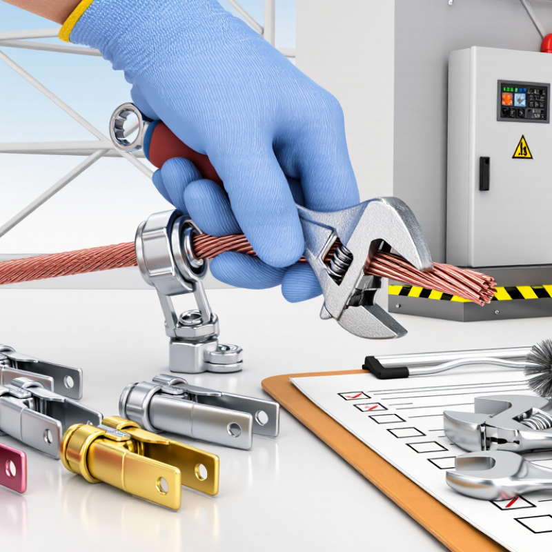
In practical installations, small details often decide long-term performance. I have seen otherwise suitable kits fail because installers ignored surface preparation, torque values, or water pathways. That mistake is easy to repeat. A reliable inspection checklist should confirm fit, bonding continuity, corrosion protection, labeling, and access for future testing. The best kit is not always the most expensive one. It is the one that matches the engineering design, installation method, and maintenance plan. When uncertainty remains, consult a qualified grounding engineer and verify the final choice through documented testing.
How to Choose the Right Grounding Kits?

Understanding the Purpose and Types of Grounding Kits

How to Choose the Right Grounding Kits?

Understanding the Purpose and Types of Grounding Kits

Grounding kits create a controlled, low-impedance path for fault current, lightning energy, and induced noise. Bonding also keeps exposed metal parts near the same electrical potential. That reduces shock risks and limits damage to connected equipment. The National Fire Protection Association’s Home Fires Involving Electrical Failure or Malfunction report estimated 35,150 related U.S. home fires annually from 2015 to 2019. These incidents caused about 470 deaths and approximately 1.3 billion dollars in property damage. Grounding is not an accessory.

Common kits serve different purposes. Equipment grounding kits connect cabinets, trays, enclosures, and structural metalwork to a grounding conductor. Shield-bonding kits terminate cable shields and help control electromagnetic interference. Lightning and surge grounding kits provide a deliberate discharge path, but they must work with the complete protection system. Telecom installations may require kits for coaxial cables, waveguides, or outdoor entry points. Each type has different connectors, conductor sizes, and weather-sealing requirements.

Choose materials that match the cable, enclosure, and installation environment. Check fault-current capacity, corrosion resistance, temperature range, and conductor compatibility. IEEE Std 80 emphasizes safe touch and step-voltage control in substations, while IEC 60364-5-54 addresses protective conductors and bonding arrangements. A low resistance reading is reassuring, but it does not prove a complete installation. That shortcut is tempting. It is also incomplete. Inspectors should verify torque, continuity, bonding points, and moisture protection before energizing equipment.


Identifying System Requirements and Installation Conditions

Choosing the right grounding kit starts with the electrical system, not the package label. Identify the conductor material, cross-sectional area, system voltage, and expected fault current. The kit must provide a low-impedance bonding path under normal and fault conditions. Check whether the connection joins cable armor, conduit, tray, or another metallic enclosure. These parts may look similar, but their bonding requirements can differ.

Installation conditions matter just as much. Record the available space, bend radius, mounting surface, and access for inspection. Moisture, salt, chemicals, vibration, and temperature changes can weaken unsuitable connections. Confirm that contact materials are compatible, especially when copper and aluminum meet. Follow the applicable electrical code and the equipment manufacturer’s installation data. Use the specified torque; guessing here is a poor shortcut. Small mistakes become hot spots.

A practical inspection should verify clean contact surfaces, secure fasteners, correct conductor routing, and visible continuity where required. Test continuity with suitable equipment, then document the result, location, date, and tester used. I have seen checklists pass while a concealed coating blocked metal-to-metal contact. That detail is easy to miss. Recheck it. If the fault level, environment, or cable construction is uncertain, involve a qualified electrical professional before selecting the kit. A kit that fits physically may still fail electrically.

How to Choose the Right Grounding Kits?

Select a grounding kit by matching the conductor cross-sectional area with the system requirements and installation conditions. The chart shows the theoretical DC resistance of copper conductors at 20°C, calculated from copper resistivity of 0.017241 Ω·mm²/m.

System requirement:
Confirm the required conductor material, cross-sectional area, fault-current duty, and applicable electrical standard.
Installation condition:
Check whether the connection is indoors, outdoors, buried, exposed to moisture, or subject to vibration and movement.
Connection quality:
Use compatible lugs, clamps, and bonding surfaces. Remove coatings where required and protect the finished connection against corrosion.

Reference values are theoretical copper conductor resistance at 20°C and exclude strand lay, joint resistance, temperature rise, and installation effects. Final sizing must follow the applicable local code and engineering design.

Comparing Materials, Compatibility, and Electrical Performance

How to Choose the Right Grounding Kits?
Comparing Materials, Compatibility, and Electrical Performance

Material selection affects both safety and service life. Bare copper conducts efficiently, but it can corrode in damp or chemical environments. Tinned copper offers better surface protection while retaining strong conductivity. Aluminum is lightweight, yet it requires compatible connectors and careful preparation. Stainless steel provides mechanical strength, although its electrical resistance may be higher. Fit matters.

Compatibility deserves close attention. The kit must match the conductor, enclosure, coating, and installation environment. Mixing dissimilar metals can create galvanic corrosion, especially where moisture collects near cable entries. Check connector ratings, conductor sizes, fault-current requirements, and applicable electrical codes. A clamp that feels secure may still damage a thin coating or leave an unreliable contact. Small details matter.

Electrical performance depends on more than a low resistance reading. The bonding path should remain continuous under vibration, heat, and fault conditions. Flexible grounding straps can handle movement better than rigid conductors near doors or hinged panels. Inspect contact surfaces for paint, oxidation, and loose hardware before testing continuity. A qualified electrician should verify the completed installation with suitable instruments. Readings can mislead when test points are poorly chosen. That is an easy mistake to make. Field conditions also change, so periodic inspection is sensible, particularly in outdoor, industrial, or high-humidity locations.

Evaluating Safety Standards, Durability, and Maintenance Needs

How to Choose the Right Grounding Kits?

A grounding kit should be judged beyond its cable size or packaging. Safety starts with recognized standards, such as IEEE 837, UL 467, IEC 60364, and local electrical codes. These references address bonding performance, material quality, fault-current paths, and installation practices. The U.S. Bureau of Labor Statistics recorded 145 workplace electrical fatalities in 2022. That figure makes grounding a life-safety decision, not a purchasing detail.

Durability depends on the installation environment. Inspect the lug, clamp, conductor, and protective coating for corrosion resistance. In outdoor substations, trapped moisture can attack metal beneath insulation. In industrial rooms, vibration may loosen connections over time. NETA maintenance guidance supports scheduled visual checks, torque verification, and electrical testing. A checklist may still miss a damaged thread or hidden oxidation. I have seen apparently clean connections fail after repeated thermal cycling. That is an uncomfortable reminder: appearance is not proof.

Tips: Match the kit to the conductor material and fault-current requirement. Confirm torque values before energizing equipment. Record resistance readings, inspection dates, and corrective work. Review them after storms, modifications, or overheating events. Maintenance intervals should reflect real conditions, not only the calendar. According to NFPA 70B, an effective electrical maintenance program is risk-based. That approach is useful, but imperfect. Site history still matters.

How to Choose the Right Grounding Kits? - Evaluating Safety Standards, Durability, and Maintenance Needs

Grounding Kit Type Typical Application Key Safety Standards to Check Electrical and Mechanical Considerations Corrosion and Durability Routine Maintenance Installation Complexity Best Selection Criteria
Copper-Bonded Ground Rod Kit Electrical service grounding, utility structures, light commercial installations, and general earthing systems. Verify compatibility with applicable requirements such as UL 467, IEC 62561-2, and local electrical codes. Confirm rod diameter, length, clamp range, conductor size, and suitability for the required fault-current path. High
Thick copper bonding over a steel core provides good mechanical strength and corrosion resistance when the coating is undamaged.
Inspect above-ground connections for looseness, mechanical damage, oxidation, and water ingress. Test continuity or earth resistance according to the site program. Moderate
Requires suitable soil preparation, driving equipment, and correct clamp installation.
Choose when a durable driven electrode is practical and the soil conditions are not excessively corrosive or rocky.
Stainless-Steel Grounding Clamp Kit Bonding conductors to pipes, structural steel, equipment frames, and grounding electrodes in corrosive or outdoor environments. Look for testing or certification applicable to grounding and bonding hardware, including IEC 62561-1 or UL 467 where relevant. Check conductor capacity, clamp range, tightening torque, contact pressure, and compatibility with the connected metals. High
Stainless steel generally performs well in humid, industrial, and coastal locations, but galvanic compatibility must still be assessed.
Check torque markings, surface condition, signs of galvanic corrosion, and whether the connection remains accessible for inspection. Low
Normally installed with standard hand tools when the mounting surface is prepared correctly.
Choose for exposed connections where mechanical strength, corrosion resistance, and simple inspection are important.
Tinned Copper Braid Bonding Kit Flexible bonding of doors, panels, cable trays, expansion joints, equipment enclosures, and moving assemblies. Confirm conductor construction, current rating, temperature rating, and compliance with the applicable installation code or equipment specification. Use a braid with adequate cross-sectional area and length. Avoid sharp bends, excessive tension, and routing that can cause abrasion. Medium to High
Tinning improves resistance to oxidation and helps reduce direct contact between copper and dissimilar metals.
Inspect braid strands, lugs, fasteners, and termination points for fraying, fatigue, looseness, and contamination. Low
Flexible connections are generally quick to install when suitable lugs and hardware are provided.
Choose where vibration, movement, hinged access, or thermal expansion could stress a rigid grounding conductor.
Exothermic-Welded Connection Kit Permanent connections between grounding conductors, electrodes, structural steel, and buried grid conductors. Use procedures and materials qualified for the project; grounding-system design should follow applicable local codes and engineering requirements. Provides a continuous metallic connection with no bolted contact interface. Follow mold, conductor-size, charge, and safety instructions precisely. High
A properly completed weld is well suited to buried environments and has no mechanical fastener to loosen.
Normally requires little routine maintenance after installation, but accessible test points and periodic system testing remain necessary. High
Requires trained personnel, heat-resistant equipment, weather control, and strict fire-safety procedures.
Choose for permanent buried joints, high-reliability systems, or locations where future access will be difficult.
Mechanical Compression Grounding Kit Bonding conductors to electrodes, busbars, structural members, and equipment where a bolted or compression connection is preferred. Check applicable requirements such as IEC 62561-1, UL 467, conductor compatibility, and the manufacturer's verified installation method. Confirm the correct die, conductor combination, compression sequence, torque, and required contact area. Medium
Performance depends heavily on correct preparation, compression quality, sealing, and protection from moisture.
Inspect for looseness, oxidation, moisture entry, deformation, and conductor pull-out. Re-torque only when permitted by the installation procedure. Moderate
Requires the correct compression tool and trained installation personnel.
Choose when a controlled, repeatable connection is required and installation access allows proper tooling.
Grounding Busbar and Bonding Link Kit Main earthing terminals, telecommunications rooms, control panels, data centers, and equipment bonding networks. Review the applicable electrical code, enclosure requirements, short-circuit withstand requirements, and project bonding design. Size the bar and links for expected fault current, conductor quantity, clearances, and available connection points. Medium
Indoor installations are generally durable; outdoor or contaminated locations require suitable plating, enclosure protection, and sealing.
Inspect fastener torque, labels, conductor identification, corrosion, and the accessibility of removable links used for testing. Low
Usually straightforward when the mounting surface and cable entry layout are prepared in advance.
Choose when multiple bonding conductors need a clear, organized, and testable termination point.
Ground Enhancement Material with Electrode Kit High-resistivity, rocky, dry, or space-constrained sites where achieving the required earth resistance with conventional electrodes is difficult. Confirm that the material is approved or accepted for the intended application and does not create unacceptable environmental or corrosion effects. Requires soil-resistivity assessment, electrode layout, moisture considerations, and verification through earth-resistance testing. Medium
Long-term performance depends on material stability, site moisture, chemical compatibility, and correct installation depth.
Periodic resistance testing is important. Inspect accessible connections and check for settlement, drying, erosion, or changes in site conditions. High
Installation may require excavation, controlled backfill, moisture management, and detailed site preparation.
Choose only after soil testing shows that conventional electrode arrangements are unlikely to meet the design target.
Selection note: Always confirm the required fault-current capacity, conductor size, environmental exposure, touch-voltage limits, soil resistivity, installation method, and inspection requirements with the applicable local code and a qualified electrical professional. A grounding kit should not be selected by material or price alone.

Selecting the Right Kit and Planning Proper Installation

How to Choose the Right Grounding Kits?

Selecting the Right Kit and Planning Proper Installation

Selecting a grounding kit starts with the system, not the catalog. Confirm conductor size, fault current, shield construction, metal type, and outdoor exposure. A kit for a copper shield may not suit an aluminum assembly. Check temperature ratings, corrosion resistance, and mechanical compatibility. Start with the fault study. IEEE Std 80-2013 evaluates grounding safety through touch and step voltage, using a 50-kilogram human-body model. That detail matters when selecting conductors and connection points. An undersized bonding path can overheat during a fault. No kit fits every site.

Installation planning should include drawings, access checks, isolation procedures, and a clear torque schedule. Keep bonding paths short and direct. Remove paint, oxidation, and dirt from contact surfaces, then protect exposed metal against moisture. Follow the kit’s tested assembly method; improvising hardware is a common and costly mistake. After installation, inspect the crimp or clamp, verify continuity, and record resistance readings under controlled conditions. NFPA 70B emphasizes documented electrical maintenance, while the U.S. Bureau of Labor Statistics reported 126 fatal occupational injuries involving electricity in 2022. That figure does not prove a grounding kit caused an incident, but it reinforces disciplined planning. I would still revisit every measurement after seasonal changes. A tidy connection can hide a weak contact.

Wordpress Social Share Plugin powered by Ultimatelysocial
Facebook
X (Twitter)
YouTube
LinkedIn
Share

Purchase Product Request

Request Pricing