What Is Circuit Board Assembly and How Does It Work?
Circuit board assembly turns a bare printed circuit board into a working electronic unit. Components are placed, soldered, inspected, and tested. The process may look like a sequence of machine steps. In reality, each stage depends on design choices, material control, and careful verification. A misplaced resistor or a weak solder joint can affect the entire product. Tiny details matter.
Demand for reliable electronics makes this work increasingly important. The World Semiconductor Trade Statistics (WSTS) November 2024 forecast projected global semiconductor sales of $627 billion in 2024, a 19% increase over 2023. That figure tracks chips, not circuit board assembly directly. Still, it signals the scale and pace of the electronics market that board manufacturers support. IPC’s IPC-A-610 standard also provides widely used criteria for assessing electronic assembly acceptability, including solder joints and component placement. Standards help, but they cannot replace sound process control. A clean-looking board is not necessarily a reliable one.
This guide explains what circuit board assembly involves and how its main methods work, from solder-paste printing to final testing. You’ll see why surface-mount technology suits dense designs, while through-hole parts remain useful where mechanical strength matters. We’ll also examine inspection, quality risks, and practical trade-offs. The process is precise, but not perfect; real production requires learning from defects and improving controls. That is part of the work.
What Circuit Board Assembly Is and What It Includes
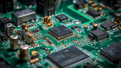
Circuit board assembly (PCBA) is the process of fitting electronic components onto a bare printed circuit board and connecting them electrically. The board provides copper pathways, while components such as resistors, capacitors, connectors, and integrated circuits perform specific functions. Assembly may use surface-mount parts, through-hole parts, or both. For surface-mount work, solder paste is applied to copper pads, components are positioned, and heat melts the paste into joints. Through-hole leads pass through drilled holes and are soldered on the other side. The exact mix depends on the design, size, and operating conditions.
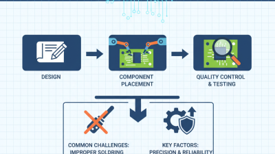
Assembly includes more than placing parts. It typically covers solder-paste application, component placement, soldering, inspection, and electrical testing. Automated optical inspection can reveal missing parts, misalignment, or visible solder defects. X-ray inspection may help assess joints hidden beneath certain packages. Testing checks whether the assembled board behaves as intended, but methods depend on product requirements. Even a slightly shifted connector can complicate installation. Process choices matter.
Tips: Confirm the component list, polarity marks, and board revision before assembly. Protect sensitive parts from static, and inspect solder joints under good lighting. A checklist helps, though it will not catch everything. Document known limitations and verify critical functions with suitable tests. One missed detail can still happen.
Core Components Used in a Circuit Board Assembly
A circuit board assembly combines a bare printed circuit board with components that control, process, and distribute electrical signals. The board provides copper pathways and mechanical support. Resistors limit current, while capacitors store energy and reduce voltage noise. Inductors manage changing current and filter unwanted signals. Diodes guide current in one direction and protect sensitive circuits. Integrated circuits perform complex tasks, such as timing, sensing, or data processing. Connectors link the assembly to cables, batteries, displays, or other boards.
Tips: Check each component’s value, orientation, and package before soldering. A misplaced diode can stop the entire circuit. Keep leads short and solder joints smooth. Cleanliness matters more than many beginners expect. Use magnification when inspecting tiny surface-mounted parts.
Assembly methods usually include surface-mount technology and through-hole mounting. Automated equipment places small components with high speed and accuracy. Through-hole parts pass through drilled holes and often provide stronger mechanical support. Solder forms both the electrical connection and physical bond. Inspection then checks alignment, solder bridges, cracked joints, and missing parts. Testing should measure power rails before full operation. That step prevents avoidable damage. In practice, even a clear schematic may hide assembly risks. Heat, vibration, and component tolerances can change performance. A reliable process records these details and improves them after every build.
How a Circuit Board Is Prepared for Assembly
A circuit board must be assembly-ready before components reach the production line. Engineers check that the bill of materials matches the latest schematic and board revision. They also verify component footprints, polarity marks, and clearances against the design files. A mismatch can leave a correctly soldered component electrically useless. Details matter.
Panel drawings need accurate board outlines, tooling holes, and fiducial marks so machines can locate each board. Engineers review stencil apertures and solder-paste deposits against component size and spacing. The International Federation of Robotics’ World Robotics 2023 report recorded 553,052 industrial robot installations worldwide in 2022, a 5% increase from 2021. This wider shift toward automation makes consistent board data especially important; it does not fix poor preparation. Small errors travel.
Before a production run, teams check incoming parts, moisture-sensitive packaging, and electrostatic-discharge controls. They confirm feeder positions and placement programs against the approved component list. IPC J-STD-001 and IPC-A-610 provide widely used requirements and acceptance criteria for soldering and finished assemblies. Yet standards cannot resolve every design trade-off. A footprint may satisfy a rule and still be awkward to inspect or rework. A short engineering review, with the fabricator and assembler, can catch that practical gap before boards are built.
How Components Are Mounted and Soldered to the Board
What Is Circuit Board Assembly and How Does It Work?
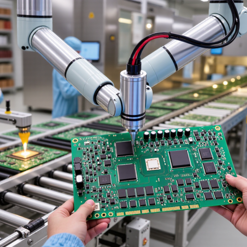
Circuit board assembly turns a bare circuit board into a working electronic unit. Components are placed according to an engineering layout and verified against the bill of materials. Most small components use surface-mount technology. A stencil spreads solder paste onto precise copper pads. A placement machine then sets resistors, capacitors, and integrated circuits onto the paste.
The populated board travels through a controlled reflow oven. Heat melts the paste and creates solid solder joints as the board cools. Larger connectors may use through-hole mounting. Their leads pass through drilled holes and are soldered on the opposite side. Technicians inspect alignment, solder coverage, and component orientation. Automated optical inspection helps find bridges, shifted parts, and missing components. X-ray inspection can reveal hidden joints beneath certain packages.
No process is perfect.
Tips: Keep the solder paste fresh and measure its thickness regularly. Follow the oven’s thermal profile, rather than guessing from temperature alone. Clean handling matters because fingerprints and dust can weaken solder performance. I have seen an apparently clean board fail because one connector had insufficient solder. Rechecking unusual results is worthwhile, even when production pressure is high. A small inspection delay can prevent costly rework and field failures.
What Is Circuit Board Assembly and How Does It Work?
A typical lead-free reflow profile shows how heat melts solder paste to form electrical and mechanical connections between surface-mount components and a printed circuit board.
This illustrative profile reaches a peak of 245°C, above the 217°C liquidus temperature of SAC305 lead-free solder. Actual profiles vary with the solder paste, components, and board design.
How a Completed Circuit Board Assembly Is Inspected and Tested
A completed circuit board assembly is checked in stages, because one test cannot reveal every defect. After solder reflow, automated optical inspection scans each board for shifted components, polarity errors, and uneven solder joints. A bright camera image may show a lifted chip lead, but it cannot reliably see hidden connections beneath a ball-grid-array package. Those joints often need X-ray inspection.
Electrical testing adds another layer. In-circuit test probes measure connections and component values, while functional testing powers the board and checks whether it behaves as designed. IPC’s North American EMS Statistical Program reports manufacturing benchmarks such as first-pass yield and defect rates. These measures help teams compare process performance; a high final pass rate alone may hide boards that needed rework.
Inspection criteria also matter. IPC-A-610 defines electronic assembly acceptability requirements, but technicians must apply the correct product class and criteria. Keep records of test results, component lots, and repairs so failures can be traced to a process step. One limitation remains: a board can pass a test and still fail later under heat or vibration. Testing should reflect the board’s actual operating conditions, not just a convenient bench setup. And inspection is not magic.