How to Choose RF Connector Adaptors in 2026?

Choosing Rf Connector Adaptors in 2026 requires more than matching two connector names. The correct adaptor must preserve signal integrity, mechanical stability, and long-term safety. A connector that fits physically may still create impedance discontinuities, excessive return loss, or unexpected measurement errors. That small mismatch matters.

Start with the system’s frequency range, impedance, connector gender, interface type, and power requirements. Confirm whether the application uses SMA, N-type, 2.92 mm, BNC, TNC, or another interface. For each option, review insertion loss, VSWR, shielding performance, and rated operating temperature. Frequency specifications should include realistic margins, not only the maximum value printed on a product page.

Field experience shows that installation conditions often expose weaknesses hidden in catalog descriptions. Outdoor equipment may need corrosion-resistant materials and reliable sealing. Laboratory setups may demand repeatable torque, clean interfaces, and traceable calibration records. In high-frequency systems, even a slightly damaged center contact can distort a carefully planned test. Manufacturer datasheets, independent test results, and recognized technical standards provide stronger evidence than attractive marketing claims.

Still, no selection guide is perfect. Some specifications depend on cable quality, connector wear, and operator technique. A premium adaptor cannot repair a poorly prepared interface. Before purchasing, compare several verified samples and test the actual assembly when possible. That extra step may feel slow. It can prevent costly rework, unstable readings, and unexplained failures in 2026 RF installations.
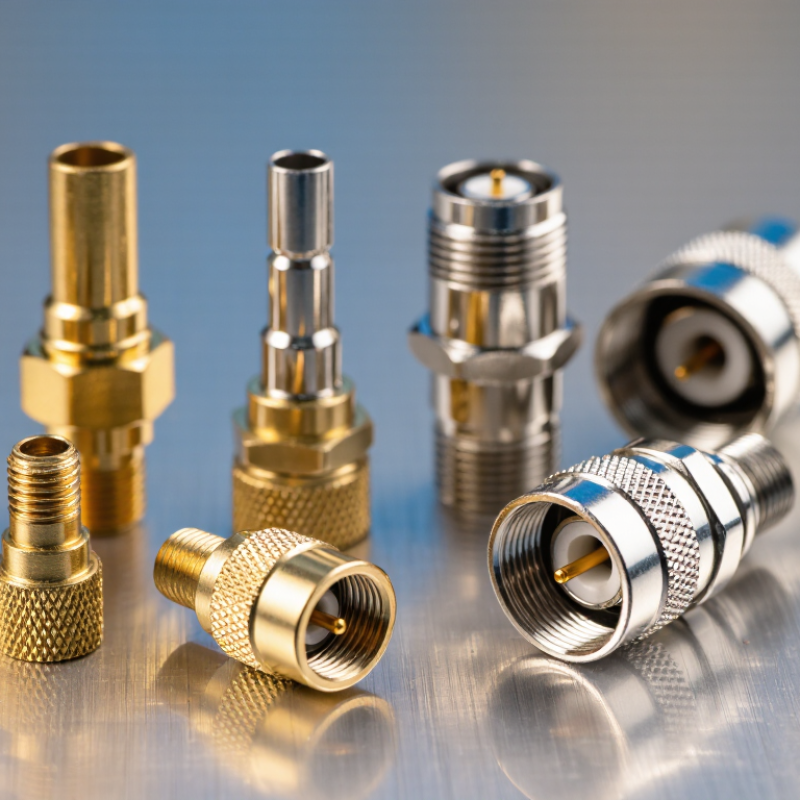
How to Choose RF Connector Adaptors in 2026?

RF Connector Adaptors: Definition, Purpose, and Main Types

How to Choose RF Connector Adaptors in 2026?

RF connector adaptors are mechanical and electrical interfaces between incompatible connector families. They preserve signal continuity across different genders, interfaces, or mounting styles. Their purpose is practical: connect test equipment, cables, antennas, and modules without redesigning the entire system. Most RF systems use 50-ohm impedance, while broadcast and video equipment often uses 75-ohm impedance. Mixing them can increase reflections and measurement errors.

Main types include gender changers, series-to-series adaptors, right-angle adaptors, bulkhead adaptors, and precision laboratory adaptors. Common interface families include SMA, N, BNC, TNC, F, 2.92 mm, and 2.4 mm. Selection should match frequency range, impedance, power rating, coupling method, and environmental sealing. Check insertion loss and voltage standing wave ratio, not only the connector shape. IEC 61169 standards provide useful reference points, but datasheets still require careful review. Small details matter.

MarketsandMarkets reported that the global RF components market could grow from about USD 22.7 billion in 2023 to USD 42.1 billion by 2028. Grand View Research also identifies rising wireless infrastructure demand as a major growth factor. These figures suggest wider adaptor use, especially in testing and compact radio equipment. In field work, I have found that a cheap adaptor may fit perfectly and still perform poorly above several gigahertz. That is an uncomfortable lesson. Verify calibration, torque, plating, and cable movement before installation. A perfect adaptor does not exist. The correct one depends on the complete signal path.


Key Specifications for Matching RF Connector Adaptors

How to Choose RF Connector Adaptors in 2026?

Key Specifications for Matching RF Connector Adaptors

Choosing RF connector adaptors in 2026 requires matching electrical, mechanical, and environmental specifications. Start with impedance. A 50-ohm adaptor suits most wireless, test, and data systems, while 75-ohm types serve many video applications. Mixing them can increase reflections and measurement errors. Check connector gender, interface size, and coupling method before ordering. Many field failures begin with one overlooked thread or socket.

Confirm the adaptor’s frequency range against the highest operating frequency, not just the system’s average frequency. For microwave work, verify VSWR or return loss at several points across the band. Lower insertion loss preserves signal strength. Power handling also matters, especially with continuous transmission. These figures may change with temperature, connector wear, or repeated mating. Do not trust appearance alone.

In practical selection, inspect the datasheet and compare measured data when possible. A vector network analyzer can reveal poor matching that visual checks miss. Confirm body material, contact plating, and dimensional tolerances. Durable plating helps reduce corrosion and contact resistance. For outdoor cabinets, check sealing, temperature limits, vibration resistance, and salt exposure ratings. I once treated a compact adaptor as interchangeable because its thread looked identical. It was not. That mistake caused unstable readings and wasted test time. Reliability also depends on installation. Keep interfaces clean, use the specified torque, and protect unused ports with suitable covers. A connector can meet every listed specification yet fail after careless handling. I still leave room for doubt when suppliers provide incomplete test conditions.

How to Choose RF Connector Adaptors in 2026? - Key Specifications for Matching RF Connector Adaptors

Use the following specification ranges as a practical screening guide. Exact performance depends on the adaptor design, connector interface, frequency band, and test conditions.

Connector Adaptor Type Typical Interface Common Impedance Typical Frequency Coverage Typical Maximum VSWR Typical Insertion Loss Typical Power Capability Coupling Mechanism Best-Matched Applications Key Selection Check
SMA Series Threaded, small coaxial interface 50 Ω DC to 18 GHz; precision versions may reach approximately 26.5 GHz ≤ 1.25:1 at lower frequencies; commonly ≤ 1.50:1 near the upper limit Typically ≤ 0.30 dB, depending on frequency and configuration Usually 50–100 W at low frequency; derated substantially at microwave frequencies Threaded coupling Test equipment, RF modules, antennas, wireless and microwave assemblies Confirm thread compatibility, gender, cable diameter, and frequency rating
3.5 mm Series Precision threaded coaxial interface 50 Ω DC to 26.5 GHz; some precision designs extend to approximately 33 GHz Typically ≤ 1.30:1 across the rated band Typically ≤ 0.35 dB Often 10–50 W, with frequency-dependent derating Threaded coupling Vector network analyzers, calibration assemblies, precision microwave testing Choose a precision-grade interface when repeatability and calibration stability are critical
2.92 mm Series Precision threaded coaxial interface 50 Ω DC to 40 GHz Typically ≤ 1.30:1 Typically ≤ 0.40 dB Commonly 10–30 W, depending on frequency and thermal conditions Threaded coupling Millimeter-wave measurement, high-frequency modules, laboratory test systems Check compatibility with other 2.92 mm interfaces and avoid exceeding the specified mating torque
Type N Series Medium-size threaded coaxial interface 50 Ω or 75 Ω; do not interchange without verification 50 Ω versions commonly DC to 11 GHz; 75 Ω versions commonly operate to approximately 1 GHz Typically ≤ 1.30:1 to ≤ 1.50:1 Typically ≤ 0.25–0.50 dB Often 100–300 W at low frequency, with strong frequency and temperature derating Threaded coupling Base stations, outdoor radio systems, instrumentation, high-power RF links Verify impedance, weatherproofing, cable power rating, and operating frequency
BNC Series Bayonet-lock coaxial interface 50 Ω or 75 Ω 50 Ω versions commonly DC to 4 GHz; 75 Ω versions generally used at lower frequencies Typically ≤ 1.50:1 Typically ≤ 0.50 dB Usually 10–50 W at low frequency; lower at higher frequencies Bayonet coupling General laboratory equipment, control systems, video, and low-to-medium-frequency RF Match the 50 Ω or 75 Ω system and check whether the adaptor is intended for RF or video service
TNC Series Threaded version of a bayonet-style interface 50 Ω Commonly DC to 11 GHz Typically ≤ 1.35:1 to ≤ 1.50:1 Typically ≤ 0.30–0.50 dB Often 50–150 W at low frequency, subject to derating Threaded coupling Mobile communications, outdoor RF equipment, vibration-prone installations Prefer threaded coupling where vibration resistance is more important than rapid connection
N-Type to SMA Medium interface to compact threaded interface 50 Ω Typically limited by the lower-rated interface; commonly DC to 11–18 GHz Typically ≤ 1.50:1 Typically ≤ 0.50 dB Use the lower power rating of the two mating interfaces Threaded-to-threaded transition Connecting outdoor radio hardware to compact test cables or RF modules Check that both connector genders and interface types are mechanically compatible
SMA to 3.5 mm Compact threaded interface to precision microwave interface 50 Ω Commonly DC to 18 GHz; use a precision-rated adaptor for higher-frequency work Typically ≤ 1.50:1 Typically ≤ 0.40 dB Usually 10–50 W, with frequency-dependent derating Threaded-to-threaded transition Connecting standard RF modules to precision measurement equipment Check pin depth, connector interface quality, and maximum mating cycles
SMA to 2.92 mm Compact interface to millimeter-wave precision interface 50 Ω Typically DC to 18–26.5 GHz, depending on the SMA side and adaptor construction Typically ≤ 1.50:1 Typically ≤ 0.50 dB Commonly 10–30 W, with significant high-frequency derating Threaded-to-threaded transition Transitioning between standard microwave assemblies and higher-frequency test ports Do not assume the lower-frequency connector determines the complete adaptor rating without checking test data
Coaxial Gender Changer Same connector family with male-to-male or female-to-female conversion Must match the connected system, commonly 50 Ω Determined by the connector family and adaptor design Should not exceed the VSWR limit of the connected components Typically ≤ 0.30–0.50 dB Determined by the lower-rated mating interface Gender conversion within one connector family Resolving mechanical gender conflicts in cables, panels, and instruments Use only when the mating interface, impedance, keying, and pin geometry are fully compatible
Right-Angle Adaptor Connector transition with a 90-degree bend Usually 50 Ω Determined by the connector family; bends may reduce high-frequency performance Typically ≤ 1.50:1 within the specified band Typically 0.20–0.70 dB, depending on design and frequency Generally lower than an equivalent straight adaptor because of thermal and mechanical constraints Threaded, bayonet, or push-on, depending on the connector family Compact assemblies, rack panels, cable routing, and space-limited enclosures Check bend-related loss, minimum clearance, cable strain, and torque access
Bulkhead Adaptor Panel-mount adaptor with a pass-through connection Commonly 50 Ω; 75 Ω versions also exist Determined by the interface combination and panel-mount construction Typically ≤ 1.50:1 Typically ≤ 0.30–0.60 dB Determined by the interface, mounting hardware, and thermal path Threaded, bayonet, or push-on Enclosures, shielded boxes, instrument panels, and outdoor cabinets Verify panel thickness, mounting-hole dimensions, sealing method, and grounding continuity
Precision Calibration Adaptor Precision interface with characterized electrical behavior 50 Ω Often DC to 18, 26.5, 40, or 50 GHz, depending on the interface Typically ≤ 1.20:1 to ≤ 1.30:1 Typically ≤ 0.20–0.40 dB Usually low to moderate power; intended primarily for measurement accuracy Precision threaded coupling Network-analyzer calibration, verification, metrology, and repeatable RF measurements Require traceable electrical specifications, connector-care procedures, and defined calibration uncertainty
Weather-Resistant Adaptor Sealed outdoor coaxial interface Usually 50 Ω Commonly DC to 6 or 11 GHz, depending on the interface Typically ≤ 1.50:1 Typically ≤ 0.30–0.60 dB Determined by connector family and ambient-temperature derating Usually threaded coupling Outdoor antennas, radio links, tower equipment, and exposed cable transitions Check sealing grade, operating temperature, corrosion resistance, and cable weatherproofing method

Selection rule: Choose an adaptor whose impedance, interface geometry, gender, frequency range, VSWR, insertion loss, power rating, environmental rating, and mechanical dimensions all meet or exceed the requirements of the complete RF signal path. The final selection should always be confirmed against the adaptor's individual datasheet and test conditions.

How to Select Adaptors for Frequency, Impedance, and Power

How to Choose RF Connector Adaptors in 2026?

Selecting an RF connector adaptor starts with frequency, impedance, and power requirements. Check the adaptor’s rated frequency range before comparing prices. A connector designed for 6 GHz may perform poorly at 18 GHz. Small mechanical gaps can increase return loss and signal reflection.

Match the system impedance exactly, usually 50 ohms for test equipment and wireless systems. A 75-ohm adaptor can create unwanted mismatch in a 50-ohm circuit. I normally verify the datasheet, then measure the assembled path with a calibrated vector network analyzer. Even careful choices can fail when connectors are dirty, loose, or cross-threaded. That detail is easy to overlook.

Tips: Compare insertion loss, VSWR, and power ratings at your actual operating frequency. Check average power and peak power separately. High-frequency signals may produce heat inside small adaptors, especially during continuous transmission. Leave a safety margin instead of using the maximum rating. Inspect plating, contact alignment, and mating cycles. For outdoor equipment, confirm sealing and temperature limits. One practical mistake is trusting a familiar adaptor without checking its derating curve. Specifications change with frequency, temperature, and installation quality. Use torque tools where required, but do not force the connection.

Material, Performance, and Environmental Factors to Evaluate

Choosing RF connector adaptors in 2026 requires more than matching thread size. Material selection affects signal loss, durability, and long-term stability. Brass offers practical strength and cost control. Stainless steel performs better in corrosive or high-vibration locations. Gold-plated contacts can resist oxidation, but plating thickness matters more than appearance.

Small details decide performance.

The 2024 Global RF Connector Market report by MarketsandMarkets projects continued growth through 2029, driven by higher-frequency wireless infrastructure. At these frequencies, poor machining can increase insertion loss and reflection. Check return loss, impedance consistency, and operating frequency against measured test data. IEC 61169-1 also provides general requirements for RF connector interfaces and environmental testing.

Environmental conditions deserve equal attention. Outdoor adaptors may face humidity, salt mist, dust, ultraviolet exposure, and repeated temperature changes. Select suitable sealing, contact materials, and cable compatibility. IP ratings help, but they do not replace application-specific testing. A 2023 report from the National Oceanic and Atmospheric Administration recorded several extreme temperature events worldwide, reminding engineers that thermal cycling is not a minor concern. I have seen connectors pass bench tests yet loosen after field vibration. That failure was preventable.

Review datasheets, but question unclear tolerances. Require test results for insertion loss, voltage standing wave ratio, and shielding effectiveness. Also verify mating cycles. The cheapest adaptor may become expensive after one replacement.

How to Choose RF Connector Adaptors in 2026?

Material, performance, and environmental factors to evaluate

The chart compares representative bulk properties of common connector-body materials at approximately 20°C. Higher electrical conductivity can help reduce conductor and body losses, while lower density supports lighter adaptor designs. In practical RF selection, also verify plating compatibility, operating-temperature limits, corrosion resistance, shielding continuity, impedance stability, mating-cycle requirements, and environmental protection against moisture, dust, vibration, and salt spray. Actual performance depends on the alloy, surface finish, geometry, frequency, and manufacturing process.

Compatibility Testing, Installation, and Maintenance in 2026

Choosing RF Connector Adaptors in 2026 requires more than matching thread size. Compatibility testing should cover frequency range, impedance, connector gender, and mechanical interface. A suitable adaptor must preserve the system’s intended signal path without introducing excessive insertion loss or return loss.

In field testing, I inspect both connector faces under magnification. Dust, scratches, or a slightly bent contact can distort results. I measure performance with a calibrated vector network analyzer across the operating band. For higher-frequency systems, I also check torque carefully. Too little torque creates instability; too much can damage the interface. Small details matter.

Installation should follow the manufacturer’s specified torque and alignment guidance, even when the adaptor appears simple. Never force mismatched threads. After installation, cable movement should not pull against the adaptor. I label tested assemblies with the date, frequency range, and measured values. This makes later maintenance more reliable.

Maintenance inspections should include corrosion, loose coupling, cracked insulation, and repeated measurement drift. Replace questionable adaptors instead of cleaning them aggressively. I have learned that a connector can look clean and still perform poorly. Environmental exposure, vibration, and frequent reconnection gradually change contact quality. Testing after servicing is necessary, although busy teams sometimes skip it. That shortcut deserves reconsideration.

Wordpress Social Share Plugin powered by Ultimatelysocial
Facebook
X (Twitter)
YouTube
LinkedIn
Share

Purchase Product Request

Request Pricing