30+ Years of Experience in PCB Design and Manufacturing


Choosing the right Pneumatic Valves can determine whether a machine runs smoothly or struggles with repeated faults. A valve may look suitable on paper, yet fail when exposed to dust, moisture, pressure changes, or rapid cycling. Real-world selection requires more than matching port size. Engineers must examine air pressure, flow demand, response time, actuator force, temperature, and installation conditions. Small details matter. A narrow tube can restrict an otherwise capable valve. An undersized exhaust path can slow a cylinder noticeably.
This guide explains how to evaluate Pneumatic Valves with practical engineering judgment. It considers directional control, solenoid operation, proportional control, materials, sealing methods, and maintenance access. Reliable decisions should come from equipment manuals, verified performance data, and recognized pneumatic safety practices, including guidance aligned with ISO 4414. Manufacturer specifications remain essential because flow ratings and pressure limits are not always measured under identical conditions. That difference is easy to overlook.
Expect some trade-offs.
A compact valve may save space but reduce flow capacity. A high-speed model may increase energy use or require cleaner air. Stainless steel can improve corrosion resistance, but it may raise cost and complicate replacement planning. There is no universal choice. The best option depends on the application, operating environment, duty cycle, and acceptable risk. Careful testing under actual conditions is still valuable, because even a well-researched selection can reveal unexpected noise, leakage, or response delays after installation.
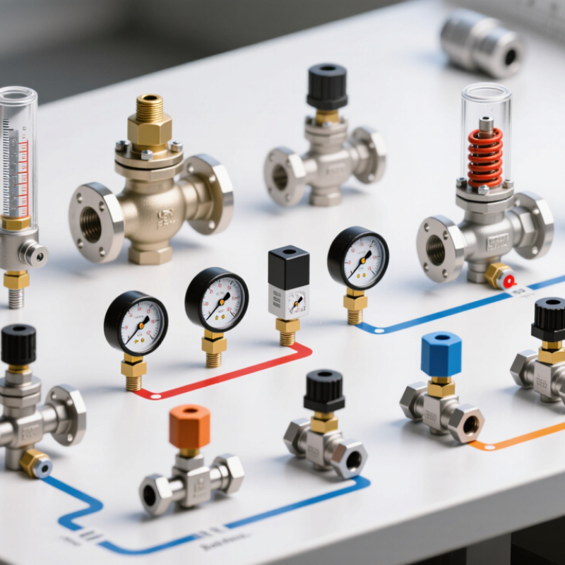
Choosing a pneumatic valve starts with the air supply, not the valve body. Measure pressure at the machine inlet during peak demand. Static gauge readings can mislead. Compressed air should be clean, dry, and properly filtered for the valve’s seals. Check water, particles, oil carryover, and ambient temperature. In one workshop, pressure dropped from 7 bar to 5.5 bar during fast cycling. The actuator became noticeably slower. Record minimum and maximum pressure, rather than only the nominal supply.
Flow requirements depend on actuator bore, stroke, cycle time, and exhaust speed. Compare valve flow ratings using the same units and test conditions. Port size alone does not prove adequate flow. I once selected a valve by port size alone. That was a mistake. The actuator stalled because fittings and mufflers created excessive restriction. Include tubing length, elbow count, silencers, and regulator capacity in the calculation. A valve with excessive flow capacity may also increase cost and make motion harder to control.
Define the complete operating envelope before choosing the valve. Note inlet pressure, working pressure, required flow, duty cycle, and expected pressure loss. Then test the system under its worst realistic load. Test the real cycle. Place a pressure gauge near the valve inlet and watch pressure while the actuator extends and retracts. If pressure falls sharply, improve the air path before changing valve size. Recheck performance after several cycles, because heat, moisture, and compressor recovery can alter the results.
| Application Profile | Typical Air Requirement | Typical Pressure Range | Recommended Valve Configuration | Typical Flow Requirement | Key Sizing and Selection Criteria | Important Design Notes |
|---|---|---|---|---|---|---|
| Single-Acting Cylinder | Compressed air for one direction; a spring returns the actuator. | Generally 3–8 bar(g), depending on the cylinder and load. | 3/2-way directional control valve, normally closed or normally open. | Usually low to medium; commonly 100–500 NL/min for small and medium cylinders. | Match the valve port size and flow coefficient to the cylinder volume and required cycle time. Confirm that the spring force can overcome the external load. | Loss of pilot or electrical power can provide a defined spring-return position when the circuit is designed correctly. |
| Double-Acting Cylinder | Compressed air is required for both extension and retraction. | Commonly 4–8 bar(g); verify the actuator’s maximum rated pressure. | 5/2-way valve for basic directional control; 5/3-way valve when a center position is needed. | Medium to high; approximately 200–1,500 NL/min is common, but larger cylinders may require more. | Use cylinder bore, stroke, operating pressure, cycle time, and required force to estimate air consumption and valve flow capacity. | For load holding, consider a center-closed circuit or separate rod-locking and safety devices where appropriate. |
| Fast Pick-and-Place Motion | High intermittent air demand caused by short cycle times and rapid actuator movement. | Often 5–7 bar(g) at the actuator inlet. | High-flow 5/2-way valve, with quick exhaust valves when suitable. | High; often above 500 NL/min, depending on cylinder size and speed. | Prioritize sufficient flow capacity, short tubing, low-restriction fittings, and correctly positioned speed-control valves. | Excessive flow can cause unstable motion. Adjust speed near the actuator and verify noise levels from quick exhaust devices. |
| Low-Speed, Smooth Actuation | Moderate air demand with precise metering during extension and retraction. | Typically 3–6 bar(g). | Standard directional valve combined with meter-out flow controls; proportional valve for advanced control. | Low to medium, determined by the desired actuator speed. | Select a valve with stable low-flow performance and use compatible flow-control components. Check minimum controllable flow. | Meter-out control is often more stable for pneumatic cylinders because it helps prevent runaway motion under varying loads. |
| Air Gripper | Intermittent air supply for opening and closing the gripper. | Commonly 4–6 bar(g), subject to gripping-force requirements. | 3/2-way valve for a single-acting gripper or 5/2-way valve for a double-acting gripper. | Low to medium; approximately 50–300 NL/min for many compact grippers. | Calculate required gripping force at the actual pressure and gripping distance. Allow a safety margin for acceleration and part variation. | Use pressure regulation and non-return or check functions where loss of air could release the workpiece. |
| Vacuum Generation | Compressed air drives a venturi vacuum generator or ejector. | Usually 4–6 bar(g) supply pressure for efficient vacuum generation. | 3/2-way supply valve, vacuum ejector valve, or integrated vacuum control valve. | Air consumption may range from approximately 20–300 NL/min; vacuum flow depends on nozzle and leakage. | Size for the required vacuum level, leakage rate, response time, and available compressed-air capacity. Do not size only by vacuum pressure. | Porous products require higher vacuum flow. Add vacuum monitoring and blow-off control when release speed is important. |
| Air Blow-Off or Cleaning | Continuous or intermittent air discharge through a nozzle or manifold. | Commonly 2–6 bar(g), based on cleaning force and noise limits. | 2/2-way on/off valve or 3/2-way valve when venting or a defined exhaust state is required. | Medium to very high; nozzle selection can create substantial demand. | Calculate nozzle flow at the operating pressure and verify that the supply piping, regulator, and compressor can maintain pressure. | Use a pressure regulator, flow restrictor, and suitable silencer where necessary. Avoid uncontrolled continuous blowing to reduce energy use. |
| Air Motor or Rotary Actuator | Continuous or rapidly changing air demand during rotation. | Often 4–7 bar(g), according to torque and speed requirements. | 5/2-way valve for bidirectional operation or 3/2-way valve for one-direction operation. | Medium to very high; confirm the motor’s rated consumption at the target speed and torque. | Use the manufacturer’s air-consumption curve, not only the nominal port size. Check valve response time and exhaust capacity. | Provide adequate filtration and lubrication only when permitted by the actuator design. Manage exhaust noise and rotational overspeed. |
| Process Isolation | Air is used to open or close a process valve; the process medium may be liquid, gas, or steam. | Actuator supply commonly 4–8 bar(g); process pressure must be evaluated separately. | 3/2-way or 5/2-way pilot valve, selected according to actuator type and required fail position. | Usually moderate; fast response may require higher pilot flow. | Determine actuator torque or thrust, required safety factor, stroking time, and fail-open or fail-closed requirement. | Valve body and seal materials must be compatible with the process medium, temperature, pressure, and corrosion conditions. |
| High-Cycle Automation | Frequent switching with repeated pressurization and exhaust cycles. | Typically 4–7 bar(g), with stable pressure at the valve inlet. | Direct-acting or pilot-operated solenoid valve rated for the required duty cycle. | Medium to high, depending on actuator volume and cycle frequency. | Check rated switching frequency, response time, coil duty cycle, seal life, allowable leakage, and heat dissipation. | Use clean, dry air. Install filtration appropriate to the valve specification and prevent liquid water from entering the circuit. |
| Safety-Critical Motion | Air supply must support controlled stopping, exhaust, or pressure retention during faults. | Often 4–8 bar(g), with monitored supply pressure. | Monitored safety exhaust valve, redundant valve arrangement, or application-specific safety circuit. | Medium to high; the exhaust rate may be critical for stopping time. | Define the safe state, maximum stopping time, residual pressure, diagnostic coverage, and required safety performance level. | Valve selection alone does not create a complete safety function. Validate the entire pneumatic and control system to applicable standards. |
| Outdoor or Harsh Environment | Air quality and environmental exposure can significantly affect service life. | Commonly 4–8 bar(g), subject to temperature and installation conditions. | Directional valve with suitable enclosure, corrosion-resistant materials, and environmental protection. | Based on actuator demand; pressure drop may increase with long or small-diameter tubing. | Check ambient temperature, humidity, dust, vibration, chemical exposure, ingress protection, and electrical connection requirements. | Use water separation, appropriate tubing, protected exhausts, and materials compatible with the environment. |
Selection reminder: Confirm the valve’s rated pressure, flow capacity, port configuration, actuation method, response time, air-quality requirements, allowable leakage, temperature range, and fail position before finalizing the design.